A wiring harness is a carefully arranged bundle of wires, terminals, connectors and protective components that carries power and signals through your product. The choices you make—wire gauge, routing, terminations and protective sleeving—directly affect reliability, manufacturability and serviceability. This guide walks through how design decisions translate into measurable outcomes like faster assembly, fewer field failures and simpler test procedures. Engineering teams, purchasing managers, founders and project leads will find step-by-step manufacturing workflows, practical design rules, and a checklist for evaluating domestic electronics manufacturers. We cover harness anatomy, core design principles, prototyping and quality gates, applicable standards, the advantages of US-based high-mix, low-to-mid-volume production, and common pitfalls with concrete mitigations. The article also shows how related services—such as PCB assembly, cable assembly, and box build—link with harness production to form turnkey solutions, with actionable lists and comparison tables to guide design and supplier decisions.
What Is a Wiring Harness and Why Is It Essential for Your Product?
A wiring harness groups wires and connectors into a predictable, serviceable assembly that speeds installation and improves repeatable performance. By routing conductors along defined paths and adding strain reliefs and insulation, harnesses limit mechanical and environmental failure modes and make the overall system more robust. Engineers use harnesses to simplify assembly, enable modular swaps of subassemblies, and keep circuits separated for safety and EMI control. Knowing how a harness performs these roles helps you prioritize design choices—like whether to add shielding or pick a particular connector family—to get the biggest reliability gains for your application.
What Are the Main Components of a Wiring Harness?
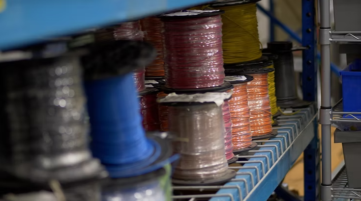
A harness is made from three core element groups: conductors (the wires), connectors and terminals, and protective materials (insulation, tubing and fastening hardware). Each element affects electrical performance and mechanical durability. Conductors set current capacity and voltage drop; connectors and terminals determine contact resistance and ease of service; sleeving and clamps prevent abrasion and control routing. Designers pick these parts based on electrical needs, environmental exposure and manufacturing limits. The table below compares common choices to help you prioritize.
Every component choice involves trade-offs between cost, flexibility and long-term reliability.
ComponentCharacteristicTypical Application Wire (copper)Gauge, strand count, insulation temperature ratingPower distribution and signal wiring Connectors & terminalsMating cycles, contact material, locking featuresServiceable modules and field-replaceable parts Insulation & tubingTemperature rating, chemical resistanceHarsh environments and sterilizable medical devices Protective hardwareTies, clamps, grommetsVibration-prone or tightly routed harnessesThis component comparison makes it easier to match materials and form factors to your application needs, and sets up the trade-offs you'll balance in the next section.
How Does a Wiring Harness Improve Electrical System Reliability?
A properly designed harness raises reliability by enforcing consistent routing, securing terminations, and adding mechanical protections that block common failure modes like chafing, loose contacts and intermittent connections. Correct specification keeps impedance predictable, reduces EMI when shielding is used, and preserves serviceability through clear connectorization and keyed housings. Including strain relief and respecting bend radii lowers fatigue at terminations, and repeatable assembly processes cut manufacturing variability that often causes early-life failures. The testing methods described later show how these features are verified before products ship.
How Do You Design a Reliable Wiring Harness? Key Principles and Best Practices
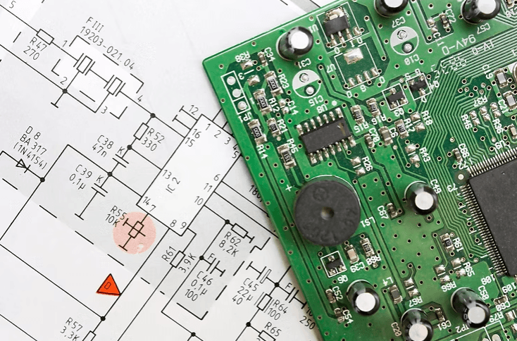
Start harness design with a clear requirements analysis that maps electrical loads, routing constraints, environmental exposure and serviceability goals into a structured specification. From there you make concrete choices—wire gauge versus current, insulation type versus temperature and chemicals, connector family versus mating cycles—that must be optimized for manufacturability and testability. Early DFM (design for manufacturability) reviews reduce rework by aligning your design with supplier capabilities and assembly processes. The short list below captures the essential practices that support long life and low defect rates.
Good design discipline then leads to specific sizing and routing rules that produce predictable behavior in production.
- Prioritize requirements: start with electrical load, voltage drop and environmental ratings.
- Design for manufacturability: limit unique parts and favor common connector families.
- Protect mechanically and electrically: add strain reliefs, respect bend radii, and use shielding where needed.
Following these guidelines reduces iteration during prototyping, speeds production transition and lowers the chance of late-stage changes.
What Are the Critical Design Considerations for Wire Harnesses?
Key considerations include choosing the correct wire gauge for current and acceptable voltage drop, picking insulation materials that withstand temperature and chemicals, enforcing routing and bend-radius limits to avoid conductor fatigue, and selecting connectors that meet mating-cycle and sealing requirements. Wire gauge affects voltage drop and heating—larger cross-section lowers resistance but increases size and cost—so you must balance space, weight and thermal performance. Connector choices influence assembly speed and field serviceability, and shielded pairs or drain wires are typical where EMI control is required. These trade-offs feed into a practical sizing and routing checklist that supports reliable manufacturing outcomes.
Design assumptions should be validated during prototyping under representative conditions.
Designing Electric Vehicle Wiring Harnesses for Cost, Serviceability, and Safety
This study focuses on designing an EV wiring harness as the central electrical network connecting vehicle components. The goal is to balance cost, serviceability and safety using precise layout tools (AutoCAD Electrical) to document harness topology and support manufacturable designs.
Design of Wiring Harness and Performance Analysis of Powertrain Using Matlab and E-Cad for Electric Vehicle, 2025
How Can You Avoid Common Wiring Harness Design Mistakes?
Typical mistakes include under-sizing wire gauges, omitting adequate strain relief and slack, selecting connectors with poor sealing or low mating cycles, and leaving out test points or harness IDs for traceability. Prevent these by holding early DFM reviews, producing harness drawings with clear termination callouts, specifying crimp inspection criteria, and planning functional and environmental tests during prototyping. A short mitigation checklist helps reduce surprises in production and keeps assembly quality consistent across batches.
Targeted prototype tests confirm whether your assumptions hold and inform production readiness and supplier choice.
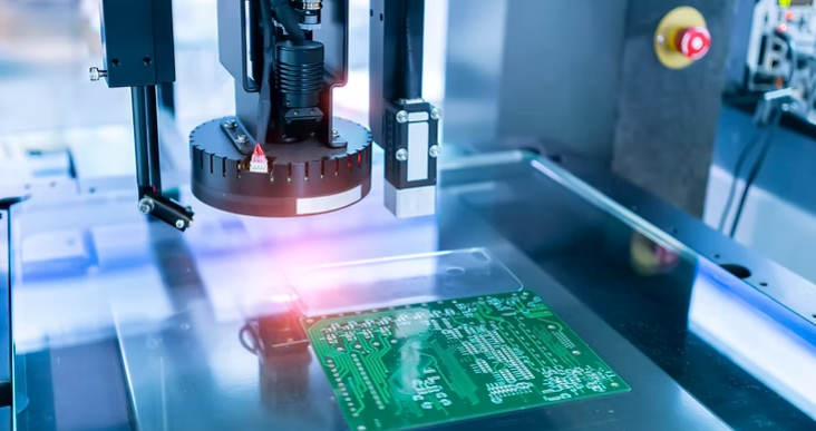
What Is the Wire Harness Assembly and Manufacturing Process? Step-by-Step Overview
Typical harness manufacturing follows a clear sequence: design review and documentation, prototype builds, wire preparation and stripping, termination (crimp or solder), assembly and bundling, electrical and mechanical testing, and final validation before production release. Each stage includes quality gates—crimp inspection, continuity and insulation tests, visual checks—that catch defects early and prevent escapes. Lead times are driven by part availability, connector lead times, batch size and assembly complexity; knowing these drivers helps set realistic schedules and MOQ expectations.
The numbered process below makes the sequence and its quality checks easy to follow.
- Design review and BOM verification: confirm parts and process documentation.
- Prototype build: validate fit, routing and basic function with a small run.
- Wire preparation: cut, strip and mark wires to spec.
- Termination: crimp or solder, followed by crimp inspection.
- Assembly and harnessing: route, sleeve and secure to mechanical housings.
- Testing: continuity, insulation resistance, hi-pot where required, and pull tests.
- Final validation: environmental and functional tests as applicable to the industry.
These steps highlight where DFM-driven changes provide the greatest benefit and introduce the in-house capabilities some US-based manufacturers use to speed design-to-production flow.
I-Tech E-Services LLC demonstrates turnkey production workflows used in high-mix, low-to-mid-volume environments. Their in-house custom cabling and wire harness services tie PCB assembly, cable assembly and box builds together to reduce coordination overhead and shorten feedback loops during prototyping and pilot runs. Centralized documentation, traceability and test data help engineering teams validate designs faster and scale into production under controlled conditions.
Bringing assembly, testing and related electromechanical services under one roof gives engineering teams a single point of contact and consistent quality gates across assemblies.
How Are Custom Wire Harnesses Prototyped and Validated?
Prototyping usually starts with a build-to-print or build-to-spec prototype to confirm mechanical fit, connector orientation and basic electrical function. Small pilot runs follow to verify assembly repeatability and identify tooling or fixture needs. Prototype validation typically includes continuity checks, functional tests with mated PCBs or subassemblies, and targeted environmental tests (thermal cycling, vibration) where the application demands it. Complexity dictates iteration count, but most projects see at least one mechanical fit and one electrical verification cycle before production.
Effective prototyping finds issues early, shortens development timelines and lowers total development cost.
What Quality Control and Testing Methods Ensure Reliable Cable Assembly?
Quality control blends electrical tests—continuity, insulation resistance, hi-pot—with mechanical checks like pull testing and visual/crimp inspection to catch common failure modes. The table below summarizes these tests, what they detect, typical acceptance criteria and when to apply them, especially in regulated industries.
Here's a practical comparison of common harness tests and their uses.
TestDetectsTypical Acceptance Criteria ContinuityOpen circuits, miswires0 Ω up to a specified maximum series resistance Insulation resistanceLeakage paths and degraded insulationMegaohm-class resistance per spec Hi-pot (dielectric)Dielectric breakdown under high voltageNo breakdown at the specified voltage and duration Pull/torque testMechanical strength of terminationsSpecified force without terminal pull-out or deformationUsing these tests together gives broad coverage of both electrical and mechanical failure modes. Regulated industries usually require documented test records and lot traceability for each run.
Which Industry Standards and Certifications Ensure Wiring Harness Quality and Compliance?
Standards and certifications define quality management, design controls and assembly requirements that affect material choices, documented processes and traceability. IPC/WHMA-A-620 sets acceptability criteria for cable and harness assemblies; AS9100D and ISO 13485:2016 certified by NQA govern quality systems for aerospace and medical suppliers respectively. ITAR registration applies where defense-related technical data and exports are involved. Understanding each standard's scope clarifies contractual and design obligations and helps you pick the right supplier.
The concise standards mapping below shows which rules influence design and manufacturing choices.
StandardScopePractical Implication IPC/WHMA-A-620Acceptability of cable and harness assembliesDirects inspection criteria and crimp workmanship AS9100DAerospace quality management systemRequires stringent process controls and audits ISO 13485:2016Medical device quality managementFocuses on design controls and traceability ITAR RegisteredControls defense-related technical data and exportsNecessitates controlled access and export complianceAutomotive systems add another layer of complexity that demands rigorous verification methods and tools to ensure the wiring network performs reliably and safely.
Verifying Wiring Harness Designs for Automotive Electrical Systems
This paper highlights the central role of the electrical wiring harness in vehicle systems, describing the harness as the physical network that distributes power and signals across many devices. It outlines verification approaches used to validate 2D and 3D harness designs and ensure integrity in complex automotive architectures.
Electrical Quantified Wiring Integrity Check Tool to Verify and Validate the Wiring Harness 2D & 3D Designs, 2016
What Are AS9100D, ISO 13485, ITAR, and IPC/WHMA-A-620 Standards?
AS9100D extends general QMS requirements with aerospace-specific controls to ensure process consistency and supplier oversight. ISO 13485:2016 certified by NQA targets medical device manufacturers with requirements for design control, traceability and risk management aligned with regulatory expectations. ITAR governs the export and handling of defense articles and technical data, requiring registered suppliers to maintain controlled access. IPC/WHMA-A-620 defines workmanship acceptance criteria for cable and harness assemblies, covering crimps, soldering, sleeving and labeling. Knowing these frameworks helps you verify that a supplier meets your industry's process and documentation obligations.
How Do I-Tech E-Services' Certifications Apply to Complex Harness Projects?
I-Tech E-Services LLC holds AS9100D, ISO 13485:2016 certified by NQA and ITAR registration, backed by IPC/WHMA-A-620-trained operators and documented inspection procedures. These credentials enable the company to build harnesses for aerospace, medical and defense programs under controlled conditions with full traceability. For customers in regulated industries, this means auditable records, consistent workmanship and compliance-ready documentation that can be submitted to end-customers or regulatory bodies. The certifications also reinforce internal process discipline that benefits any project requiring repeatable quality.
Why Choose a US-Based Manufacturer for Wiring Harness Production?
US-based production offers shorter lead times, easier communication, protection of sensitive IP and greater flexibility for design changes during NPI—especially valuable for high-mix, low-to-mid-volume programs. Domestic manufacturing reduces shipping risk and tariff exposure while supporting faster prototype cycles and real-time collaboration. For projects involving ITAR-controlled data or requiring on-site audits, a US location simplifies compliance and logistics. The trade-offs are typically higher labor cost per hour, offset by lower total cost of quality, fewer engineering iterations and faster time-to-market.
What Are the Benefits of Domestic High-Mix, Low-to-Mid-Volume Production?
High-mix, low-to-mid-volume environments suit products with multiple variants, shorter lifecycles or uncertain demand forecasts. US-based shops can handle frequent changeovers, support NPI iterations and respond quickly to ECOs without the overhead of long-distance coordination. Engineering teams benefit from proximity—faster feedback on DFM issues, tighter prototype loops and easier escalation when problems arise. This agility reduces total program cost even when piece-price appears higher on paper.
How Does Partnering with I-Tech E-Services Reduce Program Risk?
I-Tech E-Services LLC offers custom cabling and wire harness services alongside PCB assembly, box build and test services—consolidating multiple steps under one roof and one quality system. This integration shortens feedback loops, reduces hand-off errors and gives engineering teams a single point of contact for complex programs. With certifications covering aerospace, medical and defense requirements, the company can support regulated projects from prototype through production while maintaining traceable documentation and consistent workmanship.
What Common Wiring Harness Challenges Can You Prevent with Good Design?
Many harness failures trace back to preventable design or process gaps: under-sized conductors, inadequate strain relief, poor connector sealing, missing test access, and unclear documentation. Catching these issues during DFM review and prototype validation avoids costly field failures and production rework. The list below captures frequent pitfalls and their mitigations.
- Under-sized wire gauge: Calculate current and voltage drop for worst-case conditions; add margin for temperature derating.
- Missing strain relief or slack: Specify strain relief hardware and include service loops where connectors will be mated/unmated.
- Poor connector sealing: Match IP rating to environment; verify sealing in prototype testing.
- No test points or harness ID: Add continuity test access and unique harness labels for traceability.
- Incomplete documentation: Provide wiring diagrams, termination tables and assembly instructions before production.
Addressing these points early keeps production smooth and reduces warranty exposure.
How Do Related Services Like PCB Assembly, Cable Assembly, and Box Build Integrate with Harness Production?
Harnesses rarely stand alone—they connect PCBs, sensors, displays and enclosures into finished products. Coordinating harness production with PCB assembly, cable assembly and box build under one supplier simplifies scheduling, consolidates documentation and reduces interface errors. For example, having the same team build the harness and integrate it into a box build catches fit issues immediately and avoids finger-pointing between vendors. Turnkey solutions also streamline testing: functional checks can span the entire assembly rather than isolated subassemblies, catching system-level defects earlier.
What Is the Value of a Turnkey Electronics Manufacturing Partner?
A turnkey partner manages component procurement, assembly, test and logistics so engineering teams can focus on product development. Single-source accountability reduces coordination overhead and shortens time-to-market. When the same supplier handles harnesses, PCBAs and final integration, design feedback flows faster and quality gates are consistent across all assemblies. For companies without in-house manufacturing, turnkey partnerships lower capital investment and fixed overhead while maintaining process control and traceability.
Ready to Start Your Wiring Harness Project?
I-Tech E-Services LLC provides custom cabling and wire harness services for high-mix, low-to-mid-volume programs, backed by AS9100D, ISO 13485:2016 certified by NQA, and ITAR registration. From prototype through production, our in-house capabilities—PCB assembly, box build, and comprehensive testing—give you a single point of contact and consistent quality gates. Contact us to discuss your project and get a quote.