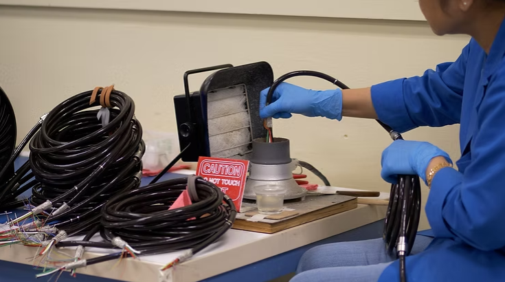
Custom cable assembly refers to purpose‑built electrical interconnects engineered to meet a product's unique electrical, mechanical and regulatory requirements. They deliver reliable signal and power where standard, off‑the‑shelf cables don't meet the system's needs.
This guide shows how custom cable assemblies and wire harnesses preserve uptime, enable traceability, and meet standards such as IPC/WHMA‑A‑620, AS9100D, ISO 13485 and ITAR for regulated programs. Engineering teams, procurement leads, founders and project managers will find practical DFM (design‑for‑manufacturability) steps, material tradeoffs, test protocols and sourcing tactics that cut rework and lifetime cost. We connect PCB assembly practices to cable reliability, outline material and test best practices, review cost drivers and supply risks, and explain when a US‑based, high‑mix, low‑to‑mid‑volume manufacturing partner is the right choice. Ahead you'll find checklists, comparison tables and clear rules‑of‑thumb to help you specify, qualify and buy cable assemblies and box builds for aerospace, medical, industrial and telecom applications.
What Is Custom Cable Assembly and Why Is It Vital for Critical Electronics?
Custom cable assembly is a tailored electrical interconnect: conductors, connectors, shielding and jackets arranged to meet a product's electrical, mechanical and regulatory constraints. By matching conductor size, insulation and shielding to the signal type and operating environment, assemblies protect signal integrity, safety and service life under real‑world stress. For critical electronics they deliver three practical benefits: stronger reliability under mechanical and thermal stress, traceable lot control for compliance, and form‑factor customization that supports compact, serviceable system designs. These qualities matter most in aerospace, medical, industrial and telecom systems where failure risks include safety incidents, expensive downtime and failed qualification. A clear grasp of these fundamentals lets teams pick cable materials, connectors and test plans that reflect system‑level risk and life‑cycle needs.
How Do Custom Cable Assemblies Differ from Wire Harnesses?
Custom cable assemblies and wire harnesses are related but distinct solutions. A cable assembly usually means pre‑terminated multi‑conductor, coaxial or fiber cables with connectors and shielding optimized for signal or power runs. A wire harness groups many single conductors, often in looms or bundles with collective jackets and terminations for internal routing. Cable assemblies are chosen where consistent impedance, shielding and connectorized mating are required; wire harnesses suit bulk internal wiring and structured routing through enclosures. The right choice depends on bend radius, serviceability, EMI needs and assembly labor tradeoffs — deciding early reduces redesign and assembly errors later.
What Are the Key Components of Reliable Cable Assemblies?
Reliable assemblies combine proven components: conductors, insulation and jackets, shielding, connectors and strain reliefs, with optional overmolds for environmental sealing and mechanical support. Conductor materials (tinned or silver‑plated copper, specialty alloys) affect conductivity and solderability; insulation (PVC, silicone, PTFE) sets temperature and chemical resistance; shielding (foil, braid or combined) controls EMI and crosstalk; connectors and terminals provide repeatable mating and retention. Every choice trades cost against performance — for example, PTFE jackets raise temperature tolerance and cost, while braid‑plus‑foil shielding improves EMI protection in noisy environments. Choosing components to match the system's electrical, mechanical and regulatory needs is the most reliable path to long service life.
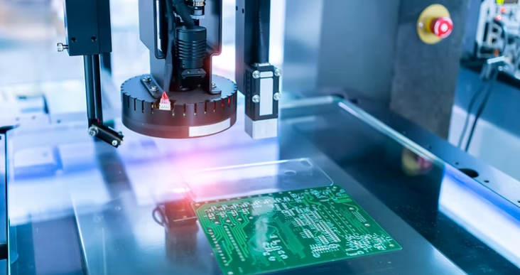
How Does PCB Assembly Impact the Reliability of Custom Cable Solutions?
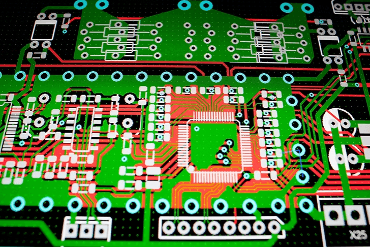
The PCB assembly is the mechanical and electrical interface for many cable terminations, so board decisions directly affect connector life, signal integrity and strain relief performance. Connector footprint, pad finish and board tolerances influence mating force, contact life and how mechanical stress transfers to cable terminations. Poor board design can lead to fretting, intermittent contacts or connector failure under vibration. Tight tolerances, clear mechanical keepouts and correct thru‑hole or SMT footprints reduce downstream issues and simplify assembly. Addressing these board details during design and assembly planning ties PCB quality to cable reliability and lowers integration rework.
What Are Common PCB Assembly Mistakes to Avoid?
Common PCB assembly mistakes that hurt cable reliability include misaligned connector placement that makes mating difficult; undersized pads or weak solder fillets that create fragile joints; and uncontrolled solder processes that produce bridging or cold joints. These defects cause intermittent signals, higher contact resistance and accelerated fatigue under vibration and thermal cycling. Catching issues early with IPC‑A‑610 visual checks, automated optical inspection and targeted X‑ray or contact‑resistance testing prevents field failures. Mitigations include correct footprint design, controlled solder‑paste deposition and defined solderability testing so every board‑to‑cable interface meets mechanical and electrical expectations.
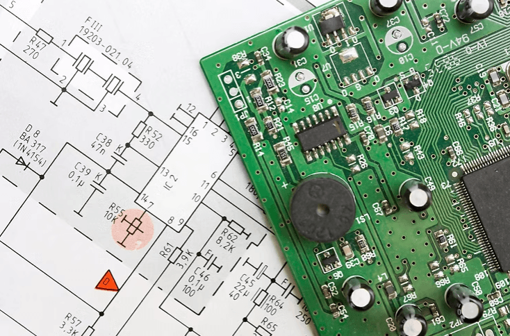
How Does Design for Manufacturability Improve PCB and Cable Assembly Quality?
Design for Manufacturability (DFM) aligns PCB layout, connector choice and cable routing to simplify assembly, speed testing and improve first‑pass yield. Practical DFM items include verifying connector mating angles, keeping minimum bend radii off board edges, adding strain‑relief anchor points and grouping signal pairs to preserve impedance. These steps reduce manual rework and protect terminations from service and shipment stresses. Running DFM reviews with your assembly partner early — focusing on connector mechanics, panel separation and test access — noticeably cuts failures and shortens qualification cycles.
What Best Practices Ensure Reliability in Custom Cable Assembly?
Reliable cable assemblies start with disciplined design, correct material selection, controlled processes and targeted testing that together validate performance under expected stresses. Begin with a DFM‑driven specification that sets electrical performance, mechanical limits, environmental ratings and traceability needs before prototyping. Choose materials and connectors based on temperature, chemical exposure and EMI requirements to avoid over‑ or under‑engineering. Finally, run a rigorous QC program — continuity, hi‑pot, pull and environmental testing — to confirm assemblies meet electrical and mechanical expectations before shipment.
Testing and inspection steps provide checkpoints for integrity and traceability through the manufacturing lifecycle.
- Design Verification: Validate electrical characteristics, connector footprints and routing constraints before tooling or production.
- Process Control: Follow documented assembly procedures and perform incoming material inspections to prevent nonconforming parts.
- Final Acceptance Testing: Execute continuity, insulation resistance (hi‑pot), pull‑force and functional tests to accept each lot.
Use this comparison to pick jackets based on mechanical and environmental priorities; the next section expands shielding and conductor choices to match signal needs.
How Does Material Selection Affect Cable Performance in Critical Environments?
Material choice sets thermal tolerance, chemical resistance, flexibility and electrical behavior, so pick materials to match the operating environment and regulatory constraints. For high‑temperature or harsh‑chemical applications, PTFE and high‑performance fluoropolymers retain dielectric properties and resist jacket breakdown. For medical devices and flexible leads, silicone or thermoplastic elastomers offer flexibility and biocompatibility. Shielding (foil, braid or combined) balances coverage, flexibility and weight — braid adds mechanical strength while foil gives continuous coverage for low‑frequency shielding. Match conductor plating (tinned vs. silver‑plated) to soldering processes and corrosion expectations to avoid contact degradation and preserve conductivity long term.
What Quality Control and Testing Methods Guarantee Cable Reliability?
A layered testing strategy catches failures at prototype and production stages before units ship. Essential tests include continuity checks for wiring correctness, hi‑pot testing for dielectric integrity, pull and torque tests for connector retention and crimp quality, and environmental tests (thermal cycling, vibration) to replicate service conditions. Enforce traceability with lot records and component‑level serialization when regulators require it. Running tests at prototype verification, incoming inspection and final acceptance helps teams find design gaps or process drift early and keeps qualification evidence ready for auditors.
What Are the Challenges and Cost Drivers in Wiring Harness and Cable Manufacturing?
Custom cable and harness manufacturing presents cost and schedule drivers that must be managed for predictable pricing and lead times. Complexity, specialized tooling (overmolds, custom connectors), extensive testing and low volumes raise unit costs and extend lead times. Sourcing risk — component obsolescence and long‑lead connectors — can force schedule slips and expensive expedite actions or redesigns. Knowing these drivers lets procurement teams make tradeoffs that lower total cost of ownership without sacrificing reliability.
Key challenges and mitigations include:
- Customization Complexity: Modularize designs and prefer industry‑standard connectors to reduce tooling needs.
- Testing Requirements: Focus early on tests that uncover the most critical failure modes.
- Sourcing Risk: Qualify alternate suppliers and maintain risk‑based safety stock to protect schedules.
This layout clarifies how different cost drivers affect price and schedule and suggests practical ways to reduce their impact.
How Can Supply Chain Disruptions and Obsolescence Be Mitigated?
Supply chain disruptions and part obsolescence raise program risk, but procurement tactics reduce exposure. Qualify alternates for critical parts, maintain formal lifecycle management and strategically stock long‑lead items to guard against supplier discontinuations. When practical, partnering with domestic US manufacturers shortens lead times and simplifies urgent rework or engineering iterations. These steps lower the chance of requalification or redesign from last‑minute substitutions and help keep deliveries predictable.
What Factors Influence Customization Costs and Production Volume?
Customization cost scales with design uniqueness, material choices and required verification. Overmolds, special shielding and connector tooling add setup cost; extensive validation increases per‑build labor. Production volume affects how NRE and tooling amortize: small batches preserve flexibility but increase unit cost, while larger runs reduce unit price but raise inventory risk. To control costs, consider modular designs, standard connectors and shared tooling strategies that retain functionality while limiting bespoke elements.
Why Choose a US‑Based, High‑Mix, Low‑to‑Mid‑Volume Electronics Manufacturing Partner?
A US‑based, high‑mix, low‑to‑mid‑volume partner gives clearer communication, closer collaboration for iterative engineering and stronger supply‑chain resilience for critical programs. Domestic partners enable frequent design reviews, easier on‑site audits and faster engineering changes that shorten development cycles and lower iteration costs. High‑mix facilities are built for flexibility, supporting many product variants without large minimums, which lets teams qualify multiple versions without oversized inventory commitments. Those operational benefits reduce risk and speed time‑to‑market for regulated, mission‑critical projects where traceability and quick response matter.
I-Tech E-Services LLC is an example of a US‑based contract electronics manufacturer offering custom cabling alongside PCB assembly, box builds, testing and turnkey services; their model emphasizes in‑house manufacturing, certified materials and open engineering access to support complex programs.
Knowing your manufacturer's philosophy and background adds confidence in their capabilities and commitment. For more on the company's mission and history, see our story.
How Do Certifications Like AS9100D, ISO 13485, and ITAR Ensure Compliance and Quality?
Certifications such as AS9100D, ISO 13485 and ITAR put formal quality systems and export controls in place that align manufacturing to aerospace, medical and defense requirements. AS9100D stresses traceability, risk management and continuous improvement for aerospace suppliers; ISO 13485 centers on medical‑device quality systems and regulatory documentation; ITAR controls handling and transfer of defense technical data and components. These frameworks establish disciplined processes for document control, supplier qualification and change management that procurement and engineering teams can rely on during supplier selection and product development.
What Services and Capabilities Should a Full‑Service Electronics CM Provide?
A full‑service contract manufacturer offers end‑to‑end support: PCB assembly, cable and harness fabrication, box‑build integration, testing, and aftermarket repair. Integrated services reduce handoffs and coordination overhead, improving traceability and time‑to‑market. Look for partners with in‑house engineering support, prototype‑to‑production flexibility and clear communication channels. Single‑source accountability simplifies quality management and warranty resolution for complex products.
How to Specify and Order Custom Cable Assemblies: A Practical Checklist
Specifying cable assemblies correctly prevents costly revisions and schedule delays. Use this checklist to capture essential requirements before requesting quotes:
- Electrical requirements: Voltage, current, impedance, shielding and signal types.
- Mechanical constraints: Length, bend radius, connector types, mounting and strain relief.
- Environmental ratings: Temperature range, chemical exposure, IP rating and flex cycles.
- Regulatory and traceability: Applicable standards (IPC/WHMA‑A‑620, AS9100D, ISO 13485, ITAR), lot control and documentation.
- Testing and acceptance: Required tests (continuity, hi‑pot, pull force) and acceptance criteria.
- Volume and schedule: Prototype and production quantities, lead‑time expectations.
A complete specification reduces quote turnaround time and prevents surprises during qualification.
Conclusion: Partnering for Reliable Custom Cable Assembly
Custom cable assemblies are critical for signal integrity, safety and service life in aerospace, medical, industrial and telecom electronics. Selecting the right materials, connectors and manufacturing partner — and applying DFM and rigorous testing — reduces rework, warranty costs and field failures. US‑based, high‑mix, low‑to‑mid‑volume partners offer flexibility, traceability and close collaboration for complex, regulated programs.
Contact i-TECH e-Services to discuss your custom cable assembly requirements and learn how our cabling and harness services can support your next project.